Postek (HK) Co., Limited | HK Series
KWQM4-4Z Hermetically Sealed Micro Switch
SPDT Changeover · Welded Metal Shell · 8 Models · -184°C to +260°C

Outline & Mounting Dimensions (mm)
1. Product Overview
The KWQM4-4Z Series is a hermetically sealed snap-action micro switch with all-welded metal shell construction. Designed for demanding aerospace, mission-critical, and industrial applications where environmental sealing and reliability are critical. Fully interchangeable with foreign equivalents of the same type.
Key Features
2. Technical Specifications
2.1 Electrical Ratings by Model 📄 Datasheet P.4
| Model | DC Voltage | Resistive | Inductive | AC 400Hz | Lamp | Temp Range | Code |
|---|---|---|---|---|---|---|---|
| HK-KWQM4-4Z | 28V DC | 5A | 3A | 115V AC, 2A | — | -184°C ~ +125°C | N |
| HK-KWQM4-4Z-1 | 28V DC | 4A | 1A | 115V AC, 2A | 0.5A | -65°C ~ +125°C | M |
| HK-KWQM4-4Z-5-1E | 28V DC | 4A | 2A* | 115V AC, 2.5A | — | -184°C ~ +260°C | E |
| HK-KWQM4-4Z-5-1J | 28V DC | 4A | — | — | — | -65°C ~ +260°C | J |
| HK-KWQM4-4Z-9-1C | 28V DC | 0.5A | 0.25A* | — | — | -184°C ~ +121°C | C |
| HK-KWQM4-4Z-9-1F | 28V DC | 0.5A | — | — | — | -65°C ~ +125°C | F |
| HK-KWQM4-4Z-11-1A | 28V DC | 3A | 1A* | 115V AC, 1A | — | -184°C ~ +121°C | A |
| HK-KWQM4-4Z-11-1G | 28V DC | 3A | — | — | — | -65°C ~ +125°C | G |
2.2 Mechanical Specifications 📄 Datasheet P.3
| Parameter | Symbol | Value |
|---|---|---|
| Operating Force | O.F. | ≤ 1.95 N |
| Release Force | R.F. | ≥ 0.28 N |
| Pretravel | P.T. | ≤ 0.76 mm |
| Movement Differential | M.D. | ≤ 0.15 mm |
| Overtravel | O.T. | ≥ 0.25 mm |
| Electrical Life | — | 100,000 cycles |
| Leakage Rate | — | ≤ 1×10⁻³ Pa·cm³/s |
| Screw Torque (Mounting) | — | ≤ 0.16 N·m |
2.3 Environmental Specifications 📄 Datasheet P.3
| Parameter | Value |
|---|---|
| Sinusoidal Vibration | 10 ~ 2000 Hz, 15 g |
| Random Vibration | 0.04 ~ 1.0 g²/Hz ASD, 119.5 m/s² Grms (Grade D) |
| Mechanical Shock | 100 g, 6 ms |
| Damp Heat (Humidity) | 10 days, per GJB 360B-2009 |
| Salt Spray (Corrosion) | 96 hours |
| Total Ionizing Dose (TID) | 100 Krad (Si) |
| Contact Bounce | ≤ 1 ms (Grade D) |
Abbreviation Glossary
- O.F. — Operating Force
- Force required to actuate the push button to operating position.
- R.F. — Release Force
- Force at which contacts return to free position.
- P.T. — Pretravel
- Distance from free position (F.P.) to operating position (O.P.).
- M.D. — Movement Differential
- Difference between operate point and release point.
- O.T. — Overtravel
- Additional travel beyond operating position.
- F.P. — Free Position
- Position when no external force is applied to actuator.
- O.P. — Operating Position
- Position where contact transfer occurs.
- TTP — Total Travel Position
- Full mechanical travel limit of the actuator.
3. Engineering Drawings
All dimensions in millimeters. Unmarked tolerances per GB/T1804-c. Click any image to view full size.


4. Model Number Nomenclature 📄 Datasheet P.5-6
| Field | Code | Description |
|---|---|---|
| Base Model | KW | Micro Switch series |
| Sealing Type | QM | Hermetically sealed, all-welded metal shell |
| Envelope Code | 4 | Round envelope, size 4 |
| Product Code | 4Z | SPDT changeover, solder lug terminal |
| Seal Rating Suffix | omitted / A / B | ≤1×10⁻³ (default) / ≤1×10⁻² / ≤1×10⁻¹ Pa·cm³/s |
| Actuator Type | 4 | Leaf spring (custom attachments available) |
| Circuit State | T / D / Z | N.O. / N.C. / SPDT Changeover |
| Electrical Code | N to G | Load rating variant — see Electrical Ratings table |
5. Quality Grades & Certifications 📄 Datasheet P.3
high-reliability industrial
Q/MA20347/Z-2019
YHYB S1201/001-2013
CASTPS04/026-2018
Q/MA30016-2019
ZZR-Q/MA20433-2019
Compliant with GJB 809B-2013 (General Spec for Micro Switches), GJB 360B-2009 (Test Methods), and GB/T1804-c (Tolerances).
6. Actuator Accessories
Accessory attachments provide lever amplification. Pretravel (P.T.), Movement Differential (M.D.), and Overtravel (O.T.) increase accordingly.
HK-ACC-025 — Roller Actuator
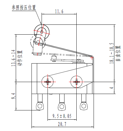
| Free Position | 18.1 ~ 18.5 mm |
| Operating Position | 13.6 ~ 14.0 mm |
| Limit Position | ≤ 13.1 mm |
HK-ACC-183 — Support Plate
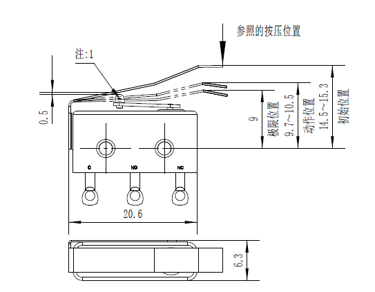
| Free Position | 14.5 ~ 15.3 mm |
| Operating Position | 9.7 ~ 10.5 mm |
| Limit Position | ≤ 9.0 mm |
HK-ACC-203 — Support Plate
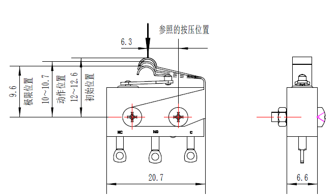
| Free Position | 12.0 ~ 12.6 mm |
| Operating Position | 10.0 ~ 10.7 mm |
| Limit Position | ≤ 9.6 mm |
HK-ACC-273 — Support Plate
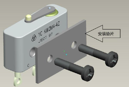
| Free Position | 13.8 ~ 14.6 mm |
| Operating Position | 9.6 ~ 10.4 mm |
| Limit Position | ≤ 9.1 mm |
7. Installation & Operating Positions
Secure using 2× M2 screws through Φ2.2 mm mounting holes. Screw torque ≤ 0.16 N·m. Use mounting washers. Do not allow adhesive or fixing agent to contact actuator mechanism.
In free state (C-NC closed), actuator lever must not contact push button. Button remains in Free Position (F.P.) under its own spring force. For correct switching, apply >1.95 N vertical downward force at P.T. + 2/3 O.T., or press to Total Travel Position (TTP) at 1.95~40 N.
- Disconnect power before installation, removal, wiring, or maintenance.
- Match switch load rating to application — using high-current switch for micro-load affects contact reliability.
- Precision device — incorrect force on push button or leaf will cause damage. Apply force perpendicular to button axis only.
- Do not exceed 40 N mechanical load on actuator.
8. Ordering & Resources
📄 Download Datasheet
Complete 22-page product datasheet with full specifications, drawings, and application notes.
Download PDF📦 Request Quote
MOQ 50–200 pcs. Samples available. 7–15 day lead time. Competitive pricing for volume orders.
✉️ [email protected]
💬 Telegram @hkpostek
📱 WhatsApp +86 180 0258 6196
🔧 Custom Configurations
Need a different actuator, terminal type, or mounting option? We offer custom leaf attachments, wire-lead termination, and application-specific adjustments.
9. Frequently Asked Questions
Is this switch suitable for high-vibration environments?
Yes. The KWQM4-4Z series meets GJB 360B-2009 sinusoidal vibration standards (10~2000 Hz, 15 g) and random vibration (0.04~1.0 g²/Hz ASD, 119.5 m/s² Grms, Grade D). The all-welded metal shell construction ensures mechanical integrity under sustained vibration.
Can I use this switch for micro-current applications?
For low-current applications, we recommend models C (0.5A) and F (0.5A). However, the manufacturer advises: "Using a high-current rated switch for micro-current applications will affect contact reliability and may cause poor contact." Please match the switch load rating to your actual application load.
What is the difference between DC and AC temperature ratings?
Several models in this series support both DC (28V) and AC 400Hz operation. The original supplier datasheet specifies different temperature ranges for each mode — for example, Model N operates at -184°C to +125°C on AC 400Hz, and -65°C to +125°C on DC. Always refer to the specific electrical code for your application.
Are RoHS, REACH, or conflict mineral declarations available?
Please contact our sales team for current compliance documentation. As a Hong Kong-based supplier serving international markets, we can provide declarations upon request for volume orders: [email protected].
Can I get samples before placing a volume order?
Yes. Samples are available for qualified inquiries. MOQ for production orders is 50–200 pcs depending on the specific model. Standard lead time is 7–15 business days. Contact us with your application requirements for sample pricing and availability.
10. Design Resources
| Resource | Format | Description | |
|---|---|---|---|
| Product Datasheet | Complete 22-page datasheet — specifications, drawings, installation, accessories | Download | |
| Engineering Drawings | PNG (×7) | Individual drawings: outline, mounting, circuit, operating positions, 4 accessories | View |
| 2D Drawings (DXF) | DXF | Available upon request — contact engineering with your specific model | Request |
| 3D Model (STEP) | STEP | 3D CAD model of the switch envelope and mounting — available upon request | Request |
11. Related Products & Applications
📚 Related Technical Articles
- How to Select Switches for -55°C to +260°C → — Thermal performance deep-dive
- Hermetic Sealing vs IP67: Which One Do You Need? → — Sealing decision framework
- EMI/RFI Shielding in Hermetic Switches → — Electromagnetic compatibility with KWQMY2 series
- How to Prevent Contact Failure Under High Vibration → — GJB 360B vibration qualification
- Long Life Cycle Switching for Railway Signal Systems → — Transport application guidance