Postek (HK) Co., Limited | VPX Series
HK-VPX Ruggedized Hybrid Electro-Optic Connector
Modular Architecture · VITA 46/48/66/67 · 6.25–10 Gbps · Press-Fit Termination
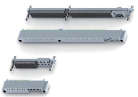
HK-VPX Connector Assembly Overview
1. Product Overview
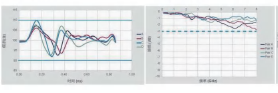
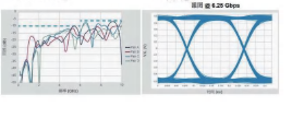
The HK-VPX Series is a ruggedized, open-architecture hybrid electro-optic connector system designed for high-reliability applications in flight systems, high-altitude platforms, and other demanding industrial environments. Conforming to VITA 41, VITA 46, VITA 48, VITA 66, and VITA 67 standards, the series provides a user-configurable, modular platform that integrates differential, single-ended, power, RF, and fiber optic signals within a single connector envelope. The high-speed differential modules utilize a solderless press-fit termination, supporting data rates up to 6.25 Gbps, extendable to 10 Gbps.
Key Features
2. Technical Specifications
2.1 General Connector Specifications 📄 Datasheet P.45–57
| Parameter | Specification |
|---|---|
| Standard Compliance | VITA 41, VITA 46, VITA 48, VITA 66, VITA 67 |
| Modular Signal Types | Differential, Single-Ended, Power, RF, Fiber Optic |
| Data Rate (Differential) | 6.25 Gbps (extendable to 10 Gbps) |
| Differential Pairs per Full Module | 32 pairs |
| Node Density | 113/inch (56 pair/inch) |
| Contact Pitch — Plug | 1.35 mm (row) × 1.8 mm (column) |
| Contact Pitch — Receptacle | 1.8 mm × 1.8 mm |
| Termination Style (Non-Fiber Modules) | Solderless press-fit |
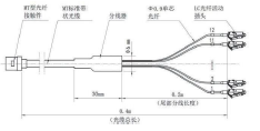
| Fiber Termination Style | MT ferrule, optical cable (default) |
| Shell Material & Plating | Aluminum alloy, nickel plating (standard); Stainless steel, passivated (optional) |
| Daughter Card Thickness (Plug) | 1.6–2.6 mm (standard); 2.6–3.5 mm (option -02) |
| Keying Positions | 8 positions per keying zone (A–H or 1–8) |
2.2 Module Type Code Reference 📄 Datasheet P.46
| Plug Code | Receptacle Code | Position | Description |
|---|---|---|---|
| a | e / f | P0 / J0 | Half module, basic module: 6 power / 16 single-ended / 4 differential pairs |
| A | I / J | P1–P6 / J1–J6 | Differential full module: 32 differential pairs / 8 single-ended |
| B | I / J | P1–P6 / J1–J6 | Single-ended full module: 80 single-ended |
| C | I / J | P1–P6 / J1–J6 | Default combination full module: 6 power / 20 single-ended / 20 differential pairs |
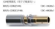
| D | D | P2–P6 / J2–J6 | 8 × #12 RF or fiber contacts (contacts ordered separately). Recommended P2 or P6. |
| G | G | P2–P6 / J2–J6 | 2 × MT fiber contacts. Recommended P2 or P6. |
| G4 | G4 | P2–P6 / J2–J6 | 4 × MT fiber contacts. Recommended P2 or P6. |
| N | N | P2–P6 / J2–J6 | 16-column blank module (filler for standard 3U/6U size) |
2.3 RF Module Specifications 📄 Datasheet P.48
| Parameter | Specification |
|---|---|
| Standard Compliance | VITA 67 |
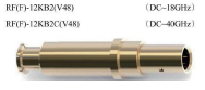
| Contact Design | Floating structure, rear insertion/removal |
| Insertion/Removal | Tool-less insertion; extraction tool QX-RF-12 (ordered separately) |
| Performance Characteristics | Stable phase and insertion loss |
| Recommended Strip Dimensions | Center conductor: 2 mm; Shield: 4.5 mm |
| Center-to-Shield Offset | 0.2+0.050 mm |
2.4 Fiber Optic Module Specifications 📄 Datasheet P.49–50
| Parameter | Specification |
|---|---|
| Standard Compliance | VITA 66 |
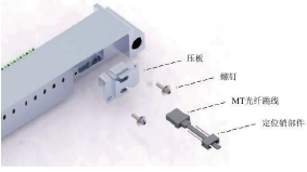
| Ferrule Type | High-density MT |
| Channels per MT Ferrule | 12 or 24 optical channels |
| Transmission Modes | Single-mode (G.652D), Single-mode (G.657A2), Multimode 62.5/125, Multimode 50/125, Multimode 50/125 (OM3) |
| Contact Engagement | Elastic contact for reliable performance under vibration and shock |
| Minimum Bend Radius | 1.27 mm (fiber); ≥ 10× cable diameter (cable assembly) |
| Installation Screw Torque | M2 screws; removable thread-locking compound recommended |
3. Nomenclature & Ordering Code
Part Number Structure
Example: VPX-61T8aAB8AAAG8-A
Example: VPX-61Z8eIJ8IIJD8-A
| Segment | Code | Description |
|---|---|---|
| Series | VPX | Ruggedized hybrid electro-optic connector series |
| Module Count | 61 | First digit = full modules (6, 2, 4, 3); Second digit = half modules (1, 0). Example: 6 full + 1 half. |
| Header/Receptacle Type | T / Z / RT / RZ / LT / LZ | T = Plug; Z = Receptacle; RT = Rear-mount plug; RZ = Rear-mount receptacle; LT = Liquid-cooled plug; LZ = Liquid-cooled receptacle |
| Keying Zone 1 | 8 | 8 keying positions (A–H). Supplied unkeyed; hardware shipped loose. |
| Module Code P0/J0 | a / e | Half module type at position P0 (plug) or J0 (receptacle) |
| Module Codes P1/J1, P2/J2 | AB / IJ | Full module types at positions P1/J1 and P2/J2. Lowercase = half module; Uppercase = full module. |
| Keying Zone 2 | 8 | 8 keying positions for P2/J2 and P3/J3 zone (6U) or P2/J2 zone (3U) |
| Module Codes P3/J3–P6/J6 | AAAG / IIJD | Full module types at positions P3/J3 through P6/J6 |
| Keying Zone 3 | 8 | 8 keying positions (1–8) for P6/J6 zone (6U only) |
| Variant Identifier | -A | A, B, C… Distinguishes contact loading variations within the same module configuration |
| Shell Material | (none) / S | None = Aluminum alloy, nickel plated; S = Stainless steel, passivated |
| Daughter Card Thickness | (none) / 02 | None = 1.6–2.6 mm; 02 = 2.6–3.5 mm (plug only) |
4. Certifications & Standards Compliance
5. Frequently Asked Questions
Are RF and fiber optic contacts included with the connector?
No. RF contacts (type D modules) and MT fiber optic contacts (type G/G4 modules) are ordered separately and are not supplied with the connector body. The extraction tool for RF contacts (QX-RF-12) is also ordered separately.
What is the default keying configuration?
Connectors are supplied unkeyed. Guide pins and guide sockets are shipped as loose hardware. The user sets the desired keying position during system assembly. Each keying zone offers 8 positions (A–H or 1–8).
Can the VPX plug mate with a standard VITA backplane receptacle?
Yes. The HK-VPX series is designed to be interoperable with standard VITA 46 receptacle connectors. The VPXP series (optimized plug variant) also mates with standard VPX series receptacles.
What is the minimum fiber bend radius during installation?
The minimum bend radius for the optical fiber is 1.27 mm. For the cable assembly, maintain a bend radius of at least 10 times the cable diameter. Avoid tight bundling that could create localized bending below these limits.
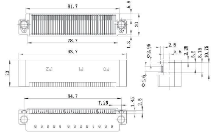
6. Dimensional Drawings & PCB Footprints
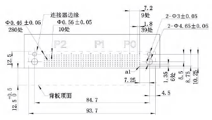
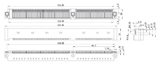
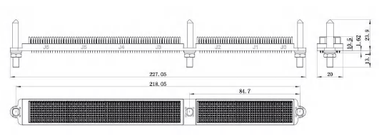
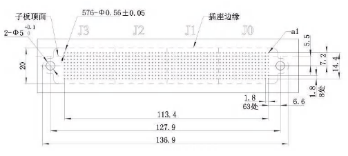
7. Resources
📚 Related Technical Articles
- EMI/RFI Shielding in Connectors — Principles and Best Practices
- Vibration & Contact Failure — Mitigation Strategies for High-Reliability Interconnects
- Hermetic Sealing vs IP67 — Understanding Environmental Protection Ratings
- Temperature Performance in Extreme Environment Components