Postek (HK) Co., Limited | HK Series
KXT/KXG High-Power Cam Rotary Switch
Cam-Actuated Rotary Switch · 12 Series · 10A–100A · Panel-Sealed
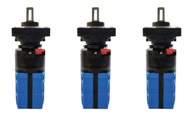
KXT Series — Cam Rotary Switch
1. Product Overview
The KXT/KXG Series is a family of cam-actuated rotary switches designed for high-current circuit switching and control in demanding industrial environments. Each switch combines a cam-driven actuation mechanism with a contact assembly in a non-shorting (break-before-make) configuration. Screw-terminal wiring throughout the range. Rated 10A to 100A across 12 series, with 1–12 switch layers and switching angles of 45°, 60°, or 90°. KXT32 and KXT63 directly replace Blue Series CA32 and CA63; KXG20/40/80/100 replace KG20/40/80/100.
Key Features
- Cam-actuated rotary mechanism — non-shorting (break-before-make) contacts
- 10A–100A rated current range across 12 series
- Panel-sealed construction with screw-terminal wiring
- 1–12 switch layers with 45°/60°/90° switching angles
- GJB1658-1993 and GJB5247-2003 qualified
- Drop-in replacement for Blue Series CA32/CA63 and KG20/40/80/100
- 10,000 cycle electrical life at rated load
2. Technical Specifications
2.1 Electrical Ratings by Series
| Series | DC Voltage | DC Current | AC Voltage | AC Current | Layers | Angle | Replaces |
|---|---|---|---|---|---|---|---|
| KXT | 28V DC | 10A / 5A | 220V AC | 10A | 1–7 | 45°/60°/90° | — |
| KXT-45-2-2D4W | 28V DC | 10A / 5A | 220V AC | 10A | 2 | 45° | — |
| KXT10 | 28V DC | 10A | 220V AC | 10A | 1–6 | 90° | — |
| KXT16 | 28V DC | 16A | 220V AC | 16A | 2–12 | 45°/90° | — |
| KXT20 | 28V DC | 20A | 220V AC | 20A | 1–6 | 90° | — |
| KXT25 | 28V DC | 25A | 220V AC | 25A | 1–6 | 90° | — |
| KXT32 | — | — | 220–380V AC | 32A | 1–6 | 90° | CA32 |
| KXT63 | — | — | 220–380V AC | 63A | 1–6 | 90° | CA63 |
| KXG20 | — | — | 220–380V AC | 20A | 1 | 90° | KG20 |
| KXG40 | — | — | 220–380V AC | 40A | 1 | 90° | KG40 |
| KXG80 | — | — | 220–380V AC | 80A | 1 | 90° | KG80 |
| KXG100 | — | — | 220–380V AC | 100A | 1 | 90° | KG100 |
2.2 Common Specifications
| Parameter | KXT / KXT10 | KXT16 | KXT20 / KXT25 | KXT32 / 63 / KXG |
|---|---|---|---|---|
| Contact Resistance | ≤0.02Ω / ≤0.01Ω | ≤0.01Ω | ≤0.01Ω | ≤0.02Ω |
| Insulation Resistance | ≥1000MΩ | ≥1000MΩ | ≥1000MΩ | ≥1000MΩ |
| Dielectric Strength (normal) | 1000V | 1000V | 1000V | 1000V |
| Dielectric Strength (12 kPa) | 600V | 600V | 600V | 200–600V |
| Switching Torque | 0.1–0.8 N·m | 0.2–1.2 N·m | 0.2–1.2 N·m | 0.2–1.2 N·m |
| Electrical Life | 10,000 cycles | 10,000 cycles | 10,000 cycles | 10,000 cycles |
| Sealing | Panel Seal | Panel Seal | Enclosed | Panel Seal |
| Termination | Screw | Screw | Screw | Screw |
2.3 Environmental Specifications
| Parameter | Value |
|---|---|
| Operating Temperature | -55°C to +85°C |
| Relative Humidity | 93±3% (40°C) |
| Sinusoidal Vibration | 10–500 Hz, 10g |
| Mechanical Shock | 50g |
| Low Pressure | 12 kPa |
| Quality Grade | J |
3. Engineering Drawings
All dimensions in millimeters. Unmarked tolerances per GB/T1804-v. Source: 大功率旋转开关.pdf
4. Model Number Nomenclature
KXT / KXT10 / KXT20 / KXT32 / KXT63
| Field | Code | Description |
|---|---|---|
| Main Model | KXT / KXT10 / KXT16 / KXT20 / KXT25 / KXT32 / KXT63 | Series identifier (includes current rating) |
| Switching Angle | 45 / 60 / 90 | Degrees per position |
| Layers | 1–12 | Number of switch decks |
| Pole/Position | □D□W (e.g. 6D2W = 6-pole 2-way) | Number of poles and positions |
| Seal | D = Panel Seal (omitted = enclosed) | Sealing type |
| Switching Mode | TD = ON-ON; ZD = Center-Off (omitted = no cutoff) | Non-shorting break-before-make |
| Mount | E = Two-hole (omitted = single-hole) | Mounting configuration |
| Faceplate | 2 = Square | Indicator plate shape |
| Color | W = Silver White; Gr = Gray | Faceplate and handle color |
Example: KXT-90-3-6D2WTD-E-2-W = 90° · 3 layers · 6-pole 2-way · ON-ON · two-hole · square · silver white
KXT16 (Extended Coding)
| Field | Code | Description |
|---|---|---|
| Main Model | KXT16 | 16A rated, 2–12 layers |
| Angle + Range | 4AA / 9GC | 4=45°, 9=90°; letters = start/end positions |
| Layers + Handle | 8A / 2B / 4HC | Layers (2–12) + Handle type (A=clockwise, B=self-return, C=positional-return) |
| Circuit Code | 001–999 | Circuit combination (see circuit table in datasheet) |
| Faceplate | S=Square; R=Rectangle | Indicator plate shape |
| Color + Lever | BL=Black, R=Red; R=Short, K=Long | Faceplate/handle color + lever length |
Example: KXT16-9AA-8A-004-RBLR = 90° · 8 layers · clockwise · circuit 004 · rectangle · black · short
5. Quality Grades & Certifications
Industrial Power Switch
GJB1658-1993 / GJB5247-2003
Series execution standards
Q/MA20274 through Q/MA20509
Blue Series compatible
KXT32→CA32, KXT63→CA63
Blue Series compatible
KXG→KG20/40/80/100
Compliant with GJB1658-1993 (General Spec for Power Rotary Switches), GJB5247-2003 (KXT16), and GB/T1804-v (Tolerances).
6. Mounting Configurations
| Series | Mounting Type | Hole Pattern | Panel Cutout |
|---|---|---|---|
| KXT | Single-hole or two-hole | φ16.2mm or 2×φ3.1mm | 20±0.1mm |
| KXT10 | M22×1.5 single-hole with lock nut | M22×1.5 threaded | φ22.3mm |
| KXT16 | Panel mount, front-access | 4×φ4.5mm, φ10mm center | 28×28mm |
| KXT20 / KXT25 | 4×M4 screws, rear-mount | 36×36mm | φ6mm shaft |
| KXT32 / KXT63 / KXG | 4×M4 screws, rear-mount | 48×48mm | φ8.3–10mm |
7. Installation & Operating Positions
Mount using the specified screws with recommended torque. Use mounting washers where provided. Ensure the actuator mechanism is free from adhesive or fixing agent contact. For multi-layer switches, ensure all decks are properly aligned before securing.
- Disconnect power before installation, removal, wiring, or maintenance.
- Match switch load rating to application — using a high-current switch for micro-load affects contact reliability.
- Apply rotational force within the specified torque range only.
- Do not exceed the rated mechanical load on the actuator.
- Verify circuit configuration against the circuit diagram before wiring.
8. Ordering & Resources
📄 Download Datasheet
Complete 39-page product manual with full specifications, drawings, circuit diagrams, and application notes.
Download PDF (2.5MB)📦 Request Quote
MOQ 50–200 pcs. Samples available. 7–15 day lead time. Competitive pricing for volume orders.
✉️ [email protected]
💬 Telegram @hkpostek
📱 WhatsApp +86 180 0258 6196
🔧 Custom Configurations
Need a specific switching angle, layer configuration, or mounting option? We offer custom circuit combinations, faceplate markings, and application-specific adjustments.
9. Frequently Asked Questions
What is a cam rotary switch and how does it differ from a standard rotary switch?
A cam rotary switch uses a cam-driven mechanism to actuate contacts, providing positive break-before-make (non-shorting) switching. Each switch deck can support multiple poles and positions, making it ideal for complex circuit transfer and multi-circuit control in a single compact assembly.
Can KXT series switches handle both AC and DC loads?
KXT through KXT25 series support both DC (28V) and AC (220V) loads. KXT32, KXT63, and all KXG series are rated for AC only (220–380V). Always verify your specific load requirements against the electrical ratings table in §2.1.
What does "panel-sealed" mean for these switches?
Panel sealing means the switch assembly is sealed against the mounting panel, preventing dust, moisture, and contaminants from entering behind the panel. The seal is achieved through a gasket or O-ring at the mounting interface. This is distinct from full hermetic sealing — panel-sealed switches are suitable for most industrial environments but not for submerged or high-pressure differential applications.
Are these switches directly interchangeable with Blue Series (CA/KG) products?
Yes. KXT32 directly replaces CA32 (90° variant) with identical 48×48mm mounting. KXT63 replaces CA63 with matching φ56mm panel cutout. KXG20/40/80/100 replace KG20/40/80/100 with 48×48mm 4-hole mounting. Electrical ratings and switching angles match the original Blue Series specifications.
How many switching layers can I order?
KXT base series supports 1–7 layers. KXT10 supports 1–6 layers. KXT16 supports 2–12 layers (the widest range). KXT20/25/32/63 support 1–6 layers. KXG series are single-deck designs with up to 4 poles. For applications requiring more than 12 layers, contact engineering for custom solutions.
10. Design Resources
| Resource | Format | Description | |
|---|---|---|---|
| Product Datasheet | Complete 39-page manual — specifications, drawings, circuit diagrams, installation | Download | |
| 2D Drawings (DXF) | DXF | Available upon request — contact engineering with your model | Request |
| 3D Model (STEP) | STEP | 3D CAD model of switch envelope and mounting — available upon request | Request |
11. Related Products & Applications
📚 Related Technical Articles
- High-Power Cam Rotary Switches: Selection Guide → — 10A–100A power distribution and motor control